
Page 52 - Market Analysis Report of Optical Communications Field in China & Global market 2025
P. 52
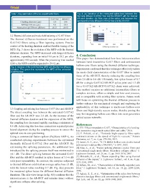
Table 1. Key parameters of the two experimental fibers.                 Fig. 4. (a) Variation of the measured splice loss between the
                                                                        thermally diffused G.657A2 fiber and the AR-HCF with the thermal
         Cladding diameter (μm)   G.657A2                AR-HCF         diffusion duration. (b) Side view of the splice joint between the
          MFD@1550 nm (μm)           125                    230         optimized thermally diffused G.657A2 fiber and the AR-HCF.
    Attenuation @1550 nm (dB/km)     9.6                   20.5
                                    ≤0.21                  ≤0.12

3.2 Thermal diffusion and mode-field tailoring of G.657 fibers          4. Conclusion
The thermal diffusion treatment was performed on the
G.657A2 fibers using a fiber tapering system. Precise                   This paper has demonstrated low-loss interconnection
control of the heating duration enabled flexible tuning of the          between bend-insensitive G.657 fibers and antiresonant
MFD. Fig. 3 shows the evolution of the MFD with the thermal             hollow-core fibers using the thermal diffusion technique.
diffusion duration. The MFD increased with longer diffusion             Experiments confirmed that this technique effectively tailors
durations, expanding from an initial 9.6 μm to 20.2 μm after            the mode-field characteristics of the G.657 fiber to match
approximately 850 seconds. When the processing time reached             those of the AR-HCF, thereby reducing the coupling loss
1200 s, the MFD could be expanded to 29.62 μm.                          from 2.6 dB to 0.6 dB. Ultimately, low splice losses of 0.7
                                                                        dB for a single G.657A2/AR-HCF splice joint and 1.5 dB
 Fig. 3. Variation of the G.657A2 fiber MFD with the thermal diffusion  for a G.657A2/AR-HCF/G.657A2 chain were achieved.
 duration. The green line represents the MFD of the untreated           This method requires no additional intermediate fibers or
 G.657A2 fiber.                                                         complex devices, offers a simple and low-cost process,
                                                                        and is compatible with existing fiber systems. Future work
3.3 Coupling and splicing loss between G.657 fiber and AR-HCF           will focus on optimizing the thermal diffusion process to
The direct coupling loss between the untreated G.657A2                  further enhance the mechanical strength and exploring the
fiber and the AR-HCF was 2.6 dB. As the increase of the                 applicability of this technique to multi-core hollow-core
thermal diffusion duration and the expansion of the MFD,                fibers and high-density access nodes, thereby paving the
the coupling loss decreased rapidly, reaching a minimum of              way for integrating hollow-core fibers into next-generation
0.6 dB. Achieving this low-loss connection required precise             optical access networks.
lateral alignment during the coupling process to ensure the
optimal core-to-core positioning.                                       References
Using a commercial fusion splicer (Fujikura 100P+), we
conducted splicing experiments between the optimized                    [1] ITU-T Recommendation G.657, “Characteristics of a bending-
thermally diffused G.657A2 fiber and the AR-HCF. By                     loss insensitive single-mode optical fibre and cable,” 2016.
optimizing the splicing parameters, the additional loss                 [2] F. Poletti, et al., “Towards high-capacity fibre-optic
introduced by the splicing process itself was minimized to              communications at the speed of light in vacuum,” Nature
≤0.1 dB. The direct splicing between the untreated G.657                Photonics, vol. 7, no. 4, pp. 279-284, 2013.
fiber and the AR-HCF resulted in splice losses of 3.3-6 dB              [3] Jasion, G. T., et al., “0.174 dB/km hollow core double nested
with poor repeatability. In contrast, the samples subjected             antiresonant nodeless fiber (DNANF),” in OFC, 2022.
to thermal diffusion exhibited an average splice loss ≤1 dB,            [4] Xiao, L., et al., “Fusion splicing photonic crystal fibers and
with the lowest value reaching 0.7 dB. Fig. 4(a) presents               conventional single-mode fibers: Microhole collapse effect,” J.
the measured splice losses for different thermal diffusion              Lightwave Technol., vol. 25, no. 11, pp. 3563-3574, 2007.
durations. The side-view image in fig. 4(b) confirms that the           [5] Shiraishi, K., et al., “Beam expanding fiber using thermal
microstructure at the AR-HCF end remains intact without                 diffusion of the dopant,” J. Lightwave Technol., vol. 8, no. 8, pp.
significant collapse after splicing.                                    1151-1161, 1990.
                                                                        [6] Kihara, M., et al., “Characteristics of thermally expanded core
                                                                        fiber,” J. Lightwave Technol., vol. 14, no. 10, pp. 2209-2214,
                                                                        1996.
                                                                        [7] Aghaie, K. Z., et al., “Optimization of the splice loss between
                                                                        photonic-bandgap fibers and conventional single-mode fibers,”
                                                                        Opt. Lett., vol. 35, no. 12, pp. 1938-1940, 2010.

50